Inverted Flex Board
NOTE 16: I got interested in the subject of shaft spines recently. It appears to be a hot subject. I measured the spine axis of a number of shafts using a spine finder and decided it would be interesting to actually measure the precise stiffness of the shafts as a function of its axial position. In other words how stiff is the shaft as it's rotated through 360 degrees?
I had this bright, but flawed, idea that if I clamped the butt of a shaft, as in a frequency analyzer, I could use a digital gram weight scale to directly measure stiffness. I placed the scale under the tip and put a V block on the scale which bent the shaft upwards about an inch. In other words I was reading the grams of force needed to deflect the shaft one inch. I rotated the shaft through 360° in 22.5° increments. I performed this test on dozens of shafts. I called this my "inverted flex board". The resulting data plots revealed some very strange results. Stiffness variations (grams per inch) ranged as high as 20% (peak to peak) on some shafts. This occurred with steel, graphite wrapped or graphite filament wound shafts. The weak axis however always lined up with the point defined by a spine finder but this range of variation seemed ridiculous. I went so far as to build four S300 shafted drivers with the strong axis of the shafts at the four cardinal positions. All the shafts were carefully matched using the "inverted flex board". There was no noticeable difference in the performance of the clubs when hit by a number of good golfers yet the stiffness plots indicated a 12% variation in stiffness on these particular shafts. The results made no sense.
I took another S300 and tested it, again getting a 12% variation. I then retested it by changing the V block height from one inch to three inches. The variation dropped to 4%! The light bulb finally went on. I chucked the shaft butt in my lathe and rotated the headstock slowly. The tip of the shaft wobbled up and down about a quarter inch even though the shafts seem to roll smoothly on a flat surface. This means that the 1 inch V block pushed the shaft upwards ¾" in one direction and 1¼" when the shaft was rotated 180 degrees. All my testing was worthless. My data were a measure of the combination of straightness and stiffness and in most cases straightness was the predominant factor.
I tried a couple of other approaches which eliminated the straightness effect but were too cumbersome to be practical.
I went back to square one and adjusted my V block such that it only pushed the tip up about half an inch. I zeroed the scale (most digital scales I've seen have a nice little zeroing feature which allows you to measure the change in weight) with this shortened V block under the shaft I then placed a one inch spacer under the V block. The new scale reading was the force to bend the shaft that additional inch and eliminated the straightness problem. It was eliminated by the first half inch and zeroing the scale. I was concerned about the linearity of the shaft stiffness. Using spacers I increased the deflection from 1/2" to 2" in 1/8" increments. The results plotted a very straight line. This was critical for my testing approach to be valid.
The new approach worked very well and while slower than my original
scale technique it wasn't too cumbersome. I improved it considerably
by just using a piece of plastic bar stock instead of a V block. I drilled
a hole in the side of the block that was about a half inch from one
end and an inch and a half from the other. With the tip in the lower
hole it pushed the shaft up a half an inch. The scale was zeroed and
the plastic block flipped 180° pushing the shaft up an additional inch.
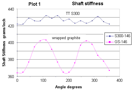
I tested two shafts, an S300 and the wrapped graphite shaft described
in Tech Note 13. Plot 1. shows the results. The S300 shows about a ±1%
variation which is close to the accuracy of the whole process. The plot
itself looks pretty much like noise. The wrapped shaft on the other
hand varied ± 5.4% and has a very sinusoidal characteristic. If you
go back to the frequency plot in Tech Note 13 you'll see the plots are
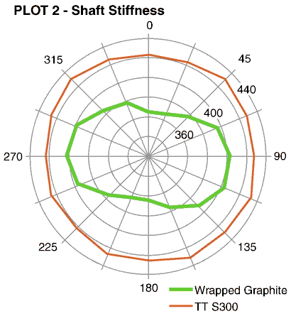
almost identical. My friend Phil Goddard suggested I display the data
in the form of a polar plot. In Plot 2. you are basically looking down
the length of the shaft and the stiffness in all directions is immediately
evident. Note the S300 is very uniform i.e. circular whereas the graphite
shaft stiffness variation is really obvious. The 12:00 position is defined
as zero degrees as determined by a spine finder. The S300 is of course
the stiffer shaft and this is obvious from these plots. The graphite
shaft plot looks like a double lobed cam. I call it a "bow tie" plot
others have characterized it as looking like a peanut. The weak and
strong axes of the shaft can be located with a frequency analyzer. In
both of these orientations the shaft will oscillate in a straight line
with little wobbling. The higher frequency will be the stiff axis the
lower the weak axis. Many of the shafts on the market today are very
good and the two frequencies are very close. I recently tested a Precision
Composite Mach 22 filament wound shaft. The stiffness plot was incredibly
uniform! It varied less than 0.3% from the average. The maximum reading
was 668 grams and the minimum 664 grams. Converted to frequency this
is just less than 1 cpm. Over a wide range of orientations the frequency
analyzer gave a max reading of 244 and a min of 243.
The graphite shaft in Plot 2 is a senior flex shaft and probably a bit too weak to do any testing in an actual club. What I hope to do is find a shaft somewhere around S or R that has similar characteristics and build up a driver. Our club is closed on Mondays except for a few of us diehards. One of these Mondays I'll take a torch, some five minute epoxy, and my head puller to the course. I'll hit balls, pull the head, rotate it 45 degrees, put it back together and hit it again. I'll go through the full 360 degrees and record the subjective results on top of a polar stiffness plot of the shaft. It should be an interesting test. Unfortunately I've been hitting my driver like a diseased monkey of late. Hopefully I'll find my swing before I try the test.
...Well it's sometime later and I still haven't found my swing but I decided to try the test anyway. I found a graphite shaft that had a reasonable "bow tie" effect with a flex between R and S. The frequency varied about 8 cpm as the shaft was rotated. I took the club, my torch, puller and five minute epoxy to the course. The results were not quite what I expected.
I tired a number of different shaft orientations and couldn't pin point an obvious best position. I was hitting into a slight wind to a soft fairway resulting in very little roll. With the stiffest direction pointed at the target, 9:00, the dispersion was reasonable tight and the average distance was 234 yards. The shots all had a bit of a fade. With the weak axis pointed at the target the average distance was 235 yards with less of a fade and a bit more dispersion. Several other orientations were tried without a significant difference. I really expected more definitive results but it could have been because I'm just not hitting the driver very well of late. Clubmakers have been reporting more obvious improvements with proper spine orientation. Some have reported that pointing the strong axis at the target (9:00) has worked the best. In this orientation the club is being bent in the direction of the spine axis in the area of ball impact. I would think the shaft would have a tendency to rotate in this orientation and produce more shot dispersion but apparently this is not the case. Maybe the improvement was the result of the stiffer axis alignment was just a better fit to the golfers swing.
Here's a summary of what I think about spines and stuff. (I could be all full of beans of course.)
- In a spine finder a bent shaft will react just as a shaft with variable stiffness.
- Steel and filament wound shafts may be bent and react in a spine finder but their true stiffness is very uniform.
- The strong and weak axes are always 90° apart.
- A shaft has two weak axes 180° apart and two strong axes also 180° apart. See the "bow-tie" in Plot 2.
- I think one of the weak axes should be pointed at the target.
- The weak and soft axes can be found with a frequency analyzer and are the non-wobbling low and high frequency positions.
- The better the shaft the less important is spine aligning.
- Every shaft has two natural frequencies that are always 90° apart. In good shafts these two frequencies are very close, 1 or 2 cpms.
If my swing gets straightened out I'll try some additional field spine alignment testing again. I think school's still out on the subject of spines...Well more time has passed and I've come to the conclusion my shafts are just too stiff for me. I've been hitting a GBB light head with a UST Pro Force 75 shaft. It has no noticeable spine and a stiffness just below S flex. One day I hit it fine the next it goes from right to right. I decided to try a softer shaft. I found a cheap wrapped shaft that had a frequency variation of almost a full flex. The weak axis was between senior and regular. I pointed this soft axis at 9:00 (weak axis in the swing plane that is, pointed at the target). No more right to rights and a really good feel. I hope to rotate the shaft 90° and see if I can feel a difference. Unfortunately will the difference be due to the spine orientation or the change in stiffness.